Muon Spin Rotation- and Relaxation under hydrostatic external pressure
Principle - Pictures - Manual
Two main considerations
determine the construction of a high pressure µSR spectrometer:
- µSR measurements require relatively large sample sizes.
- True hydrostatic conditions must prevail since internal stresses can seriously affect the µSR spectrum. For example, a wide distribution of internal fields will damp out the signal so rapidely that it can not properly observed.
The only solution is a gas pressure cell. Our system uses compressed He gas up to 1.4 GPa. The pressure cell is made of hardened CuBe. The cell can be cooled down to 10 K by a closed cycle refrigerator. Helium solidifies in the low temperature - high pressure regime attainable with the system. Solid helium, fortunatebly, cannot support significant shear forces and consequently the all important hydrostatic conditions are not seriously violated.
The schematic arrangement of the system is shown in fig.1:
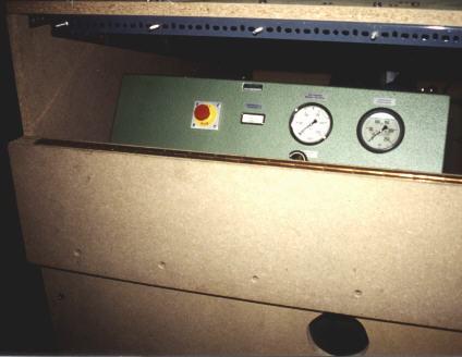
All high pressure components are mounted inside the radiation control area of the muon beam. Access is possible only if both, beam and high pressure are shut off. The apparatus is operated from a control panel outside the zone via electropneumatic valves.
Gas compression is accomplished in two steps:
- First, the gas from a He bottle (200 bar = 20 MPa) is compressed to 0.3 GPa by a two stage serial membrane compressor (NOVA SWISS, Effretikon, CH) and stored in a 100 cm3 high pressure container. This membrane compressor switches on and off automatically and thus maintains the storage pressure at all times. The He bottle is protected against overload by a safeta valve set at 250 bar. Another safety valve set at 0.3 GPa prevents overloading of the storage vessel.
- The He gas is fed to the high pressure side of a piston system, the so-called pressure intensifier (HARWOOD) which has an area ratio of 63:1. The 0.3 GPa gas pushes the piston into the down position. A check valve at the inlet to the intensifier ensures that no backflow is possible to the low pressure side. In moving the intensifier piston upwards further gas compression is achieved. This compression is done by the action of a water cooled hydraulic oil compressor working on the low pressure side of the intensifier. A flow regulator adjusts the speed of compression. A pressure regulator allows the setting of any oil pressure between 0 and 225 bar. The adjustment of the hydraulic oil pressure determines (mainly by the intensifier ration 63:1) the gas pressure on the high pressure side. When the piston has reached the top position the oil pressure is released and the piston automatically moves to the down position under the action of the compressed gas on the high pressure side. Then another stroke can be performed. A safety valve in the hydraulic oil side prevents the generation of pressures exceeding 1.4 GPa.
The high pressure gas is fed into the pressure cell via a check valve and an insulating valve. Both valves are mounted to keep the pressure in the cell when the pressure in the rest of the system is released. The pressure is measured by a transducer. A 2 cm3 gas storage consisting of a 2m long 12M tube (HARWOOD) on the 1.4 GPa side of the insulationg valve help to stabilize the pressure upon cooling the high pressure cell. After equilibration the pressure is stable for several days.
Discharge of the system down to He bottle pressure is performed via electro-pneumatic relief valves which connect directly back into the bottle. For complete relief to atmospheric pressure the He bottle is closed and the gas released into open air.
 |
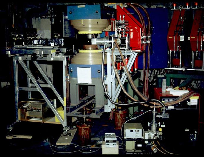
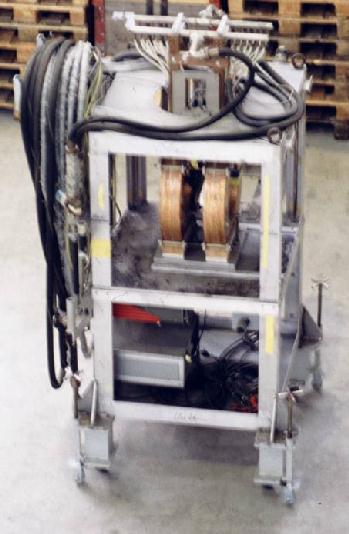
Experimenteller Aufbau
mit "Eisenjoch-Spektrometer" (ZF, TF)
- links: Detektorsystem
- Szintillationszähler,
- Lichtleiter &
- Photomultiplier
- mitte: Eisenjochmagnet (max 1 T)
- rechts: Closed cycled refrigerator
|
 |
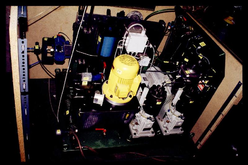
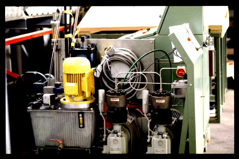
Hochdruckanlage mit Ölpumpe (gelb), Pressure Intensifier (blau), zwei Membrankompressoren (rechts) und elektro-pneumatischen Ventilen (linke Abb., links) |
 |
| Detektoranordnung:
M (incoming myons)
Bo (Backward outer)
Bi (Backward inner)
S (stopped myons)
Fi (Forward inner)
Fo (Forward outer)
|

|
 |
| Kontroll- bzw. Steuerpulte |
 |
 |